Digital Logic in Practice - The Donut Factory
Nov 07, 2025
By Robert Walsh
Digital logic can be a tricky thing to wrap one's head around. Unlike other types of electronic circuits where the overall purpose may often be perceived by simply looking at the components, integrated circuits (ICs) are literal black boxes. For example, many people would recognize a push button and maybe even a light emitting diode (LED). Some could spot a resistor, transistor, or capacitor. However, as the name suggests, the circuitry that differentiates one IC from another is integrated into the construction of the chip itself. Many different ICs may share the same form factor. In other words, they have the same shape and number of pins, so without looking at the part numbers and possibly even researching to find the data sheets, one cannot determine the specific purpose of an individual IC.
Circuits made from digital logic chips, many of which are called logic gates, are very common in everyday life. They are cheap to construct and to operate, and they power everything from home appliances to industrial machinery and even our cars, phones, tablets, and computers.
In this article, I'll describe a practical application of digital logic. This example is based on an exercise in Hands-On Digital Logic Design: Learning Through Experimentation (Kendall Hunt Publishing, 2024), a textbook on digital logic written by Professor Oren Z. Gall who teaches in the School of Electrical Engineering and Computer Science at the Pennsylvania State University. Incidentally, Professor Gall invented the Digital Evaluation Board (or DEB) which is the foundation of (and is included with) our Introduction to Digital Logic course.
Making Donuts!

Imagine that you own a donut factory, and that you have very strict standards for what you consider to be acceptable donuts to offer your customers. One component of this quality control involves the size and weight of each donut. To help ensure all the donuts produced in your factory get your stamp of approval, you've installed sensors at various points along the conveyor that moves the donuts from the ovens to the packaging area.
Specifically, one sensor measures whether a donut is too light, another whether it is too small, and the third whether it is too big. One that is both too light and too small cannot be sold, and neither can one that is too big. Put more succinctly, a donut is rejected if it is either too light AND too small OR it is too big.
These sensors are binary devices. This means that they are always in only one of two possible states. For simplicity, we'll assign numbers to these states. A one means the sensor is triggered, and a zero means it is not. For example, for the sensor that gauges weight, the sensor will read 1 if the donut is too light, and it will read 0 if the donut is of an acceptable weight.
Automating the Process
To increase productivity and to reduce the possibility of human error, you decide to automate the process of determining whether a donut is good enough to sell. You want to feed the sensor information into a system that can then indicate automatically whether to accept to reject the donut.

One part of the system needs to look at the states of the first two sensors, and if both are 1 (meaning the donut is too light and too small), then the donut is rejected. Another part of the system needs to look at the state of the third sensor, and if it is 1, the donut is also rejected. However, the system somehow needs to combine the output states of the two systems into a single output state indicating whether the donut is acceptable. Remember, if it is either too light AND too small OR it is too big, then it is rejected.
The AND gate and the OR gate
Two very common digital logic chips are the AND gate and the OR gate. An AND gate takes two input values (which may be 0 or 1) and outputs a one only if both the inputs are one. We can summarize this in what's called a truth table.
| A | B | A AND B |
|---|---|---|
| 0 | 0 | 0 |
| 1 | 0 | 0 |
| 0 | 1 | 0 |
| 1 | 1 | 1 |
This may be easier to grasp if you substitute true for 1 and false for 0. If we let A represent "it is sunny", and we let B represent "it is hot", the only way for the combination of A and B (e.g., it is both sunny and hot) to be true is for both A and B to be true independently.
For an OR gate, either condition may be true for the combined (or compound) condition to be true. Here's the truth table for A OR B:
| A | B | A OR B |
|---|---|---|
| 0 | 0 | 0 |
| 1 | 0 | 1 |
| 0 | 1 | 1 |
| 1 | 1 | 1 |
Using the same weather example, if A is "it is sunny" and B is "it is hot", then A or B is "it is either sunny or it is hot". It could be sunny and cold, or it could be cloudy and hot, but in either case the compound A OR B would still be true because at least one of the individual conditions was true.
Putting it together
We can construct a truth table for our complete donut sensor system.
| Too Light? | Too Small? | Too Light AND Too Small? | Too Big? | (Too Light AND Too Small) OR Too Big? |
|---|---|---|---|---|
| 0 | 0 | 0 | 0 | 0 |
| 1 | 0 | 0 | 0 | 0 |
| 0 | 1 | 0 | 0 | 0 |
| 1 | 1 | 1 | 0 | 1 |
| 0 | 0 | 0 | 1 | 1 |
| 1 | 0 | 0 | 1 | 1 |
| 0 | 1 | 0 | 1 | 1 |
| 1 | 1 | 1 | 1 | 1 |
You may notice that we had to add extra rows. Since there are three independent conditions, each of which may have two values (0 or 1), there are eight possible combinations. The general rule is that there are two raised to the number of conditions (e.g., 23) outcomes. The third and the fifth columns are not independent conditions. Instead, they are combinations of other conditions - too light AND too small, (too light AND too small) OR too big.
From Truth Table to Schematic Diagram
Electrical engineers use diagrams called schematics to communicate information that would be difficult to explain with natural language. After all, a picture is worth a thousand words! There are specific symbols to represent different logic gates. The following shows a schematic for the system that could implement the logic needed to determine whether a donut should be accepted or rejected. (Ignore the blue circle! It has no relevance to the diagram).
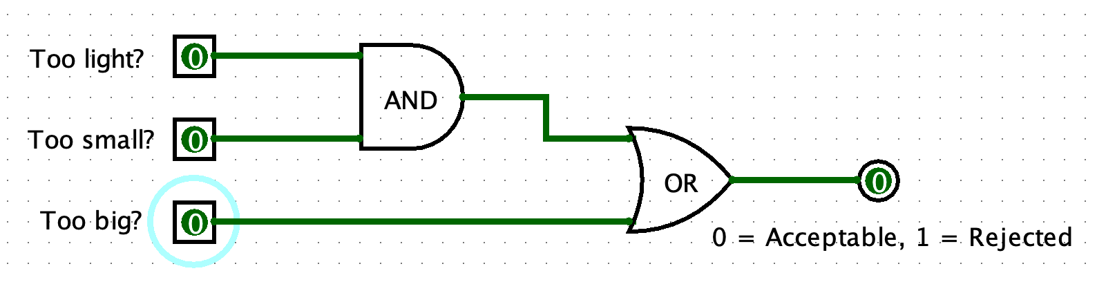
Since all of the sensors are in the untriggered state (e.g., have a value of 0), the donut is acceptable! However, if the donut is both too light and too small, then it should be rejected.
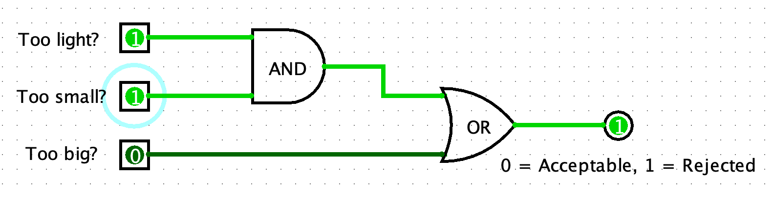
What other combinations of the input values would cause the donut to be rejected?
From Schematic Diagram to Physical Circuit
Using the DEB, we can build an actual circuit based on the schematic. The DEB has four input switches, so we can use three of these for the three sensor values. Two of these switch (or sensor) values will be inputs to an AND gate. The third switch (or sensor) will be an input to an OR gate. The other input to the OR gate is the output of the AND gate! The output of the OR gate indicates whether the donut should be accepted or rejected.

In the model shown above, LEDs have been added to provide a visual indication of the state of the sensors as well as the final determination for whether the donut makes the grade. The red LEDs on the left of the model are controlled directly by the input switches on the DEB. However, the green LEDs should always be in the opposite state! If the red LED is on, the corresponding green LED should be off, and vice versa. To implement this with the DEB, the input switch values are connected both to the appropriate red LED and also as the input value to a NOT gate. A NOT gate simply outputs the opposite of its input, so 0 becomes 1 and 1 becomes 0. Again, think true and false: not true is false, and not false is true.
The final two LEDs are driven by the output of the OR gate. Again, the output is connected directly to the red LED, but it is sent as input to another NOT gate to get the correct value for the green LED.
This donut is unacceptable because the values of the first two sensors (too light and too small) are both 1.
Other Types of Logic Gates and Digital Logic Chips
In addition to AND, OR, and NOT gates, there are several other kinds of gates, including the XOR (exclusive or which translates to one or the other but not both), NAND (a combination of NOT and AND), and NOR (a combination of NOT and OR). There are even more sophisticated digital logic chips (like flip flops) that combine gates to form more complex functionality like the ability to store (or remember) information over time.
Modern computers are composed of millions or even billions of these chips! A D-Flip Flop, for example, can store only a single bit of information (exactly one 0 or 1), so it would take 8,192 D-Flip Flops to make up just 1KB (kilobyte) of computer memory. To put this into perspective, a byte is eight bits, and one kilobyte is 1,024 bytes; thus 8x1024=8192. Computers today typically have eight or more gigabytes (8+ GB) of memory. It takes 1,024 kilobytes to make a megabyte (MB), and it takes 1,024 megabytes to make a gigabyte (GB). You do the math!
Careers in Digital Logic
Digital logic is the branch of electrical engineering that deals with designing circuits to implement the types of logical rules used in this example. Any student wanting to write computer software or to design automated control systems would benefit from learning at least the fundamentals associated with digital logic and logic gates. Zip Recruiter lists jobs titles like hardware engineer, embedded systems developer, and digital circuit designer among those that require an understanding of digital logic, and it estimates an average annual salary of around $140k in the US. Current listings at Indeed.com are similar.
So, even though the form and function of a circuit involving digital logic may seem more complex and less apparent than with other areas of electronics, understanding integrated circuits opens up many new types of applications and entire career fields. Why not take a dip into the digital logic pool and see what you think?
Stay connected with news and updates!
Join our mailing list to receive the latest news and updates from our team.
Don't worry, your information will not be shared.
We hate SPAM. We will never sell your information, for any reason.
